Bit-serial arithmetic
Bit-serial multiplier of Chen and Willoner
Bit-serial arithmetic is used in signal processing and in parallel processing where chip area and interconnection width are central issues.
Here, a bit-serial multiplier is presented that was found by Sips [Sips 82] and, independently, by Strader and Rhyne [SR 82] and by Gnanasekaran [Gna 83]. It is based on a multiplication scheme (Figure 1a) that was first used by Chen and Willoner [CW 79].
Multiplication algorithm
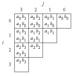
For the multiplication of two n-bit numbers a = an-1, ..., a0 and b = bn-1, ..., b0, the bit products shown in Figure 1a for the case n = 4 have to be computed and added appropriately.


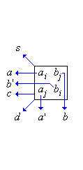
Figure 1: Bit products of a 4-bit multiplication (a), data flow of variables (b)
In the multiplication algorithm, for all index pairs (i,j) with i ≤ j, two bit products ai bj and aj bi, or if i = j one bit product ai bi, and three intermediate result bits are added, producing three new intermediate result bits. Since five bits are added, resulting in a value of possibly 5, three bits are necessary to represent the result. The boolean function that performs this operation is called (5,3)-counter, since it counts how many of its 5 inputs are 1 and represents that number by 3 output bits.1)
At each index position (i,j), the bit products ai bj and aj bi and the other three intermediate result bits that are added have binary values 2i+j. The result bits produced are a sum bit s of binary value 2i+j, a first order carry bit c of binary value 2i+j+1, and a second order carry bit d of binary value 2i+j+2.
The result bits are propagated to some other index positions where bit products of the corresponding binary values are computed. Figure 1b shows the propagation of the result bits and of the input bits. This leads to the recurrence equations below.
In order to embed the input bits into the two-dimensional index space, we set
| ai,j | = | ai |
| bi,j | = | bj |
| a'i,j | = | aj |
| b'i,j | = | bi |
for all i, j ∈ {0, ..., n-1}, i ≤ j.
Here, ai,j and bi,j stand for the upper input bits in each box of Figure 1 and a'i,j and b'i,j stand for the lower input bits. For example, the term a0 b3 corresponds to a0,3 b0,3, and a3 b0 corresponds to a'0,3 b'0,3.
Now we have the following recurrence equations. The functions S are symmetric boolean functions defined as follows:
Sk is 1 if exactly k of its arguments are 1, otherwise it is 0. Sk,m is an abbreviation of Sk ∨ Sm. Together, S1,3,5, S2,3 and S4,5 form a (5,3)-counter.
| ai,j+1 | = | ai,j |
| bi+1,j | = | bi,j |
| a'i+1,j | = | a'i,j |
| b'i,j+1 | = | b'i,j |
| si-1,j+1 | = | S1,3,5 (ai,j bi,j , a'i,j b'i,j , si,j , ci,j , di,j) |
| ci,j+1 | = | S2,3 (same arguments as above) |
| di+1,j+1 | = | S4,5 (same arguments as above) |
The result of the multiplication are the bits rj = s-1,j+1 with j = 0, ..., 2n-1. This means that the index space shown in Figure 1a has to be extended such that the sum bits and carry bits are propagated to index positions with j ≥ n. The input bits a'i,j and bi,j are 0 for j ≥ n.
Index space transformation
In order to derive the multiplier circuit from the recurrence equations, a linear transformation T is chosen that transforms the above index space {(i,j)} into the index space {(t,p)} of time and a linear array of processing elements [MF 86].
The linear transformation
| i | j | |||||
| T = | t | 0 | 1 | |||
| p | 1 | 0 |
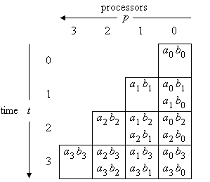
essentially transposes the scheme of Figure 1. The result is the following scheme (Figure 2). It can be seen that e.g. a0 b1 and a1 b0 are computed at time 1 in processor 0.

Figure 2: Transformed index space
Additional n time steps are necessary to shift the higher significant result bits out of the processor array. Application of the transformation T to index (-1,j+1) of a result bit gives (j+1,-1), i.e. the result bits appear at processor -1 (i.e. at the output of processor 0) at time j+1 (j = 0, ..., 2n-1).
The data dependency matrix D of the recurrences in the index space {(i,j)} is
| s | c | d | a | b | a' | b' | ||||||||||
| D = | i | -1 | 0 | 1 | 0 | 1 | 1 | 0 | ||||||||
| j | 1 | 1 | 1 | 1 | 0 | 0 | 1 |
The data dependencies express the fact that, e.g., variable s computed at index (i,j) is next used at index (i-1,j+1), or variable b produced at index (i,j) is next used at index (i,j+1).
The transformed data dependencies express the data flow in time and processor space. We have
| s | c | d | a | b | a' | b' | ||||||||||
| TD = | t | 1 | 1 | 1 | 1 | 0 | 0 | 1 | ||||||||
| p | -1 | 0 | 1 | 0 | 1 | 1 | 0 |
For instance, s is passed to the previous processor in one time step, c is held in the same processor for one time step, d is passed to the next processor in one time step. The input values b and a' are passed to the next processor in 0 time steps – this means that they are broadcast to all processors.
The input variables a and b' are held in the same processor in each time step. Thus, this input has to be provided in a bit-parallel way. However, a timing analysis shows that a0 and b'0 are first needed at time 0, a1 and b'1 are first needed at time 1, and so on. Therefore, the input is provided bit-serially and latched by a control signal at the appropriate time steps.
Multiplier unit
Figure 3 shows the multiplier, here for an operand length of n = 3. Each of the n processor elements consists of two latches where the input bits a and b' are stored, two AND-gates that compute the bit products, a (5,3)-counter, and four delay cells.
At time k in processor k only one bit product ak bk is added (see Figure 2). In this situation, the other bit product is set to 0 by the control signal.
It is possible to perform an addition simultaneously using the d-input of processor 0 (input bits s0 s1 s2 in Figure 3), so that the multiplier computes r = s + a·b.

Figure 3: Multiplier circuit for operand length n=3
Conclusions
The bit-serial multiplier of [Sips 82][SR 82][Gna 83] presented here uses n processors and requires time 2n. Chen and Willoner [CW 79] originally found the underlying multiplication scheme. However, in their implementation they used a different transformation T, namely
| i | j | |||||
| T = | t | 0 | 1 | |||
| p | 1 | 1 |
resulting in a less optimal design with 2n processors.
References
[CW 79] I.N. Chen, R. Willoner: An
[Gna 83] R. Gnanasekaran: On a Bit-Serial Input and Bit-Serial Output Multiplier. IEEE Transactions on Computers C-32, 9, 878-880 (1983)
[MF 86] D.I. Moldovan, J.A.B. Fortes: Partitioning and Mapping Algorithms into Fixed Size Systolic Arrays. IEEE Transactions on Computers C-35, 1, 1-12 (1986)
[Sips 82] H.J. Sips: Comments on "An O(n) Parallel Multiplier with Bit-Sequential Input and Output". IEEE Transactions on Computers C-31, 4, 325-327 (1982)
[SR 82] N.R. Strader, V.T. Rhyne: A Canonical Bit-Sequential Multiplier. IEEE Transactions on Computers C-31, 8, 791-795 (1982)
1) A standard full adder is a (3,2)-counter
Next: [up]
H.W. Lang mail@hwlang.de Impressum Datenschutz
Created: 01.04.2003 Updated: 08.02.2023